3D modelled and printed right leg sub-assembly: first attempt

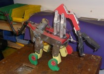
Previously the legs have been made manually in a variety of ways: cut out of polyethylene boards, soldered together using steel rods and laser cut out of  MDF. A couple of examples are shown in the photo below:

The leg sub-assembly has been redesigned to be 3D printed.

The right leg was 3D modelled:

The design followed on from that developed on the manual version.

The leg, motor and claw assembly model is shown below:

The leg was 3D printed in grey PLA (0.15mm resolution):

Some other parts of the leg sub-assembly were printed and are shown below along with the 200:1 motor/gearbox:

The long round spigot attaches to the rectangular motor spindle:

The motor and spindle attached to the leg:

The motor clamp was attached (nb: screws need trimming).

This worked but was later modified as shown below.

Red version: modifying the front legs and claws

The original ‘Robokiller’ featured a kind of flatpack design (easy to cut out) which is why I ended up using low density polyethylene boards.  The legs were left rectangular-looking (i.e., not shaped to look more leg-like) so that it would be easy to modify them later to incorporate hinges. The hinge would allow the legs to fold when ‘injured’ -more on that in subsequent posts.


DSCF7723

This post is about making a simple modification to the front legs and claws.

The shape of the legs was altered and larger claws were made (each with simple slip clutches).


DSCF7729

In the image above the right front leg and claw have been altered.

The photos below shows both legs and claws altered.


DSCF7739


DSCF7737

DSCF7740

The new claws can be seen in action below.


More later : the front legs will be modified to enable ‘injuring’ during fights….


Upgrading the ‘baby’ : first step, making claws with a slip-clutch

The ‘baby’ one was originally made with quite wide legs/claws made using ‘Polymorph’ (nylon-like material that can be shaped by hand when heated) …

DSCF6879

These looked quite effective but it was found that a cam type shape is better and puts less strain on the motor and gearbox as the loading is more gradual.

The above Polymorph claws were quite wide, hence the wide red spindles shown below.

DSCF6501

I decided to replace these with simple flat plastic cam-type claws as shown above (in line with the other versions) and incorporating a simple slip-clutch mechanism so as to avoid damaging the motor gearboxes.

DSCF6530a

The image above shows the claw which as it is allowed to slip, needs to be retained on the spindle. This has been done with a split-pin (cotter pin).

The image below shows the simple clip-clutch, achieved by cutting a slot and adding a screw to pinch the claw on the red shaft.

DSCF6776a

The modified prototype is shown below.

DSCF6519

The next task is to rework the drive mechanism, that is, to change the worm and wheel for a crank mechanism (again, with a slip-clutch).